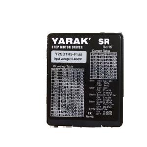
Y2SD1R5 PLUS 3.0A 2 Phase Open Loop Mini Stepper Drive with Alarm Output for Nema 8 to 23 Hybrid Stepper Motors
1. Products Overview
This YSD1R5 Plus mini stepper driver is Alarm Signal Output supported based on Y2SD1R5, which enables controllers to receive driver and motor real time status information online.
Same as Y2SD1R5, Y2SD1R5 PLUS is also special in small size and low heating, which especially suitable for applications which has limit space and low heating requirments, such as medical equipments, aerospace devices, labroatry devices, electronics equipments, chemical testing facilities, etc.
A step motor driver is a motion control driver that receives control singles and output proper driving current for a stepper motor and control its movement. Step motor and driver constitute a stepping motion control system, and the performance not only depends on the stepper motor, but also the stepper driver.
The control signal of the step drive mainly includes the pulse plus direction type, CW CCW type, external IO signal speed control type, fieldbus control type, such as EtherCAT, CanOpen, Profit net, etc.
Based on stepper motors with or without encoders, the step drivers can be divided into open-loop stepper motor drivers and closed-loop stepper motor drivers. Generally speaking, the closed-loop stepping system has better performance, such as great improvement in step loss, heating, output torque etc. However, with the development of technology, the open-loop steppers also have satisfactory and enough performance in many applications.
Based on the control principles, the step drivers are divided into analog stepper drivers and digital stepper drivers.
Although the analog step motor drive can basically meet the needs of some applications and is widely used in automated equipment in various industries. However, people have also discovered that analog stepping drivers have some problems that are difficult to solve. For example, when working at a low speed, a resonance will happen, especially when integrated with the mechanical structure, the resonance and noise will be more serious. In addition, analog stepper driver cannot perform well at high speed, such as no more than 700-800rpm, so that it cannot be used in many industrial automation applications. In addition, in terms of anti-interference capability, analog stepper driver performance is not very good, such as step loss is common when an analog stepper driver installed close to VFD or other devices which need big current.
Digital stepper drivers adopt DSP for signal processing and control for better performance and flexible application oriented customization. The basic functions of the DSP is to do voltage & current, and precise control of the motor motion through well designed control algorithm. The maximum difference between the analog and digital stepper driver is that the digital one can effectively reduce the vibration, noise and heating of the step motor, especially under low speed and low micro stepping (subdivision) conditions. Generally the digital stepper drivers have better performance than the analog one.
2. Main Technical Specifications
| Item | Description |
| Input Voltage | 12 to 48VDC |
| Output Current | 0.4 to 3.0A (Peak) |
| Control Mode | Pulse and Direction, CW &CCW |
| Control Signal | 5VDC and 24VDC Compatible |
| Micro Step Range | 16 Types, 1-128 Micro Step Settings, From 200 to 25600 Pules/Round |
| Idle Current | 50% or 90% by Setting Jumpers |
| Special Functions | Auto Tuning, Self Test, Micro Step Interpolation, Load Inertia Selection |
| Input signal Filtering | 150KHz Digital Filtering for Low Micro Step Scenarios 2MHz Digital Filtering for High Micro Step Scenarios |
| Protection | Metal, High EMC Performance, Multi-Level Electrical Protection |
| Matching Motors | Adaptive to Stepper Motors of Nema11 to Nema23 |
3. Stepper Driver External Interfaces

4. LED Status Indicator Description
Based on LED status indicators, driver working status or abnormal causes can be identified.
5. Output Current Settings
| Switch Settings | Peak Current /A |
| SW1 | SW2 | SW3 |
| Off | Off | Off | 3.0 |
| On | Off | Off | 2.7 |
| Off | On | Off | 2.4 |
| On | On | Off | 2.0 |
| Off | Off | On | 1.6 |
| On | Off | On | 1.2 |
| Off | On | On | 0.8 |
| On | On | On | 0.4 |
Idel current can be set as 50% of nromal by set SW4 ON and 90% when OFF.
6. DIP Switch Seetings
| SW5 | SW6 | SW7 | SW8 | Microsteps | PPR |
| OFF | OFF | OFF | 0 FF | 125 | 25000 |
| ON | OFF | OFF | 0 FF | 100 | 20000 |
| OFF | ON | OFF | 0 FF | 50 | 10000 |
| ON | ON | OFF | 0 FF | 40 | 8000 |
| OFF | OFF | ON | 0 FF | 25 | 5000 |
| ON | OFF | ON | 0 FF | 20 | 4000 |
| OFF | ON | ON | 0 FF | 10 | 2000 |
| ON | ON | ON | 0 FF | 5 | 1000 |
| OFF | OFF | OFF | 0 N | 128 | 25600 |
| ON | OFF | OFF | 0 N | 64 | 12800 |
| OFF | ON | OFF | 0 N | 32 | 6400 |
| ON | ON | OFF | 0 N | 16 | 3200 |
| OFF | OFF | ON | 0 N | 8 | 1600 |
| ON | OFF | ON | 0 N | 4 | 800 |
| OFF | ON | ON | 0 N | 2 | 400 |
| ON | ON | ON | 0 N | 1 | 200 |
7. Other DIP Settings
| DIP no. | Function | Description |
| SW9 | Self Test | On: motor will rotate at 1rpm/s for 1 round clockwise and 1 round back. |
| SW10 | Micro Step Interpolation | On: Micro Step Interpolation enabled, suggest to use when micro step is less then 8. Off: Function disenabled. |
| SW11 | Pulse Mode Selection | On: CW and CCW Off: Pulse and Direction |
| SW12 | Input Signal Digital Filtering | On: 150kHz, suitable for low micro step settings Off: 2MHz, suitable for high micro step settings |
8. Control Signals
Input signals descriptions as the followings,
| Display | Terminal name | Function |
| STEP | Pulse signal | Receive 5-24V/NPN/PNP signal |
| DIR | Direction signal | Receive 5-24V/NPN/PNP signal |
| EN | Enable signal | Receive 5-24V/NPN/PNP signal; EN no input, motor enable |
9. Connections
Input control signals connections as bellow,
Output alarm signals connections as bellow,
10. Mechcanical Dimenssions